
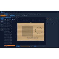
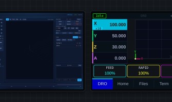
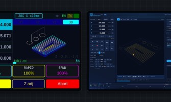
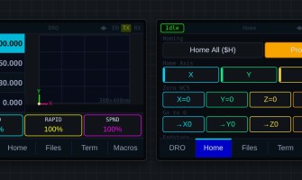
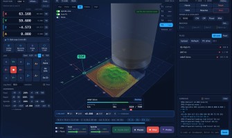
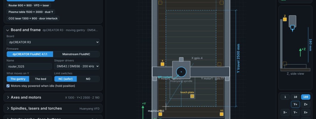
The Machine builder writes the config.yaml for your machine and draws the machine it describes, to scale. Choose the board, the axes, the spindles and lasers, and what goes on each input and output. Every change is checked against the firmware's own list of settings and the pin rules of the chip, so the file it gives you loads without errors.
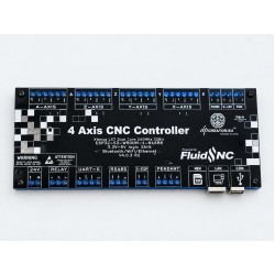
It is made for the dpCREATOR R3, and it also works with any ESP32 or ESP32-S3 board where you set the pins yourself, for dpCREATOR FluidNC or mainstream FluidNC. It runs in your browser: nothing is sent anywhere.
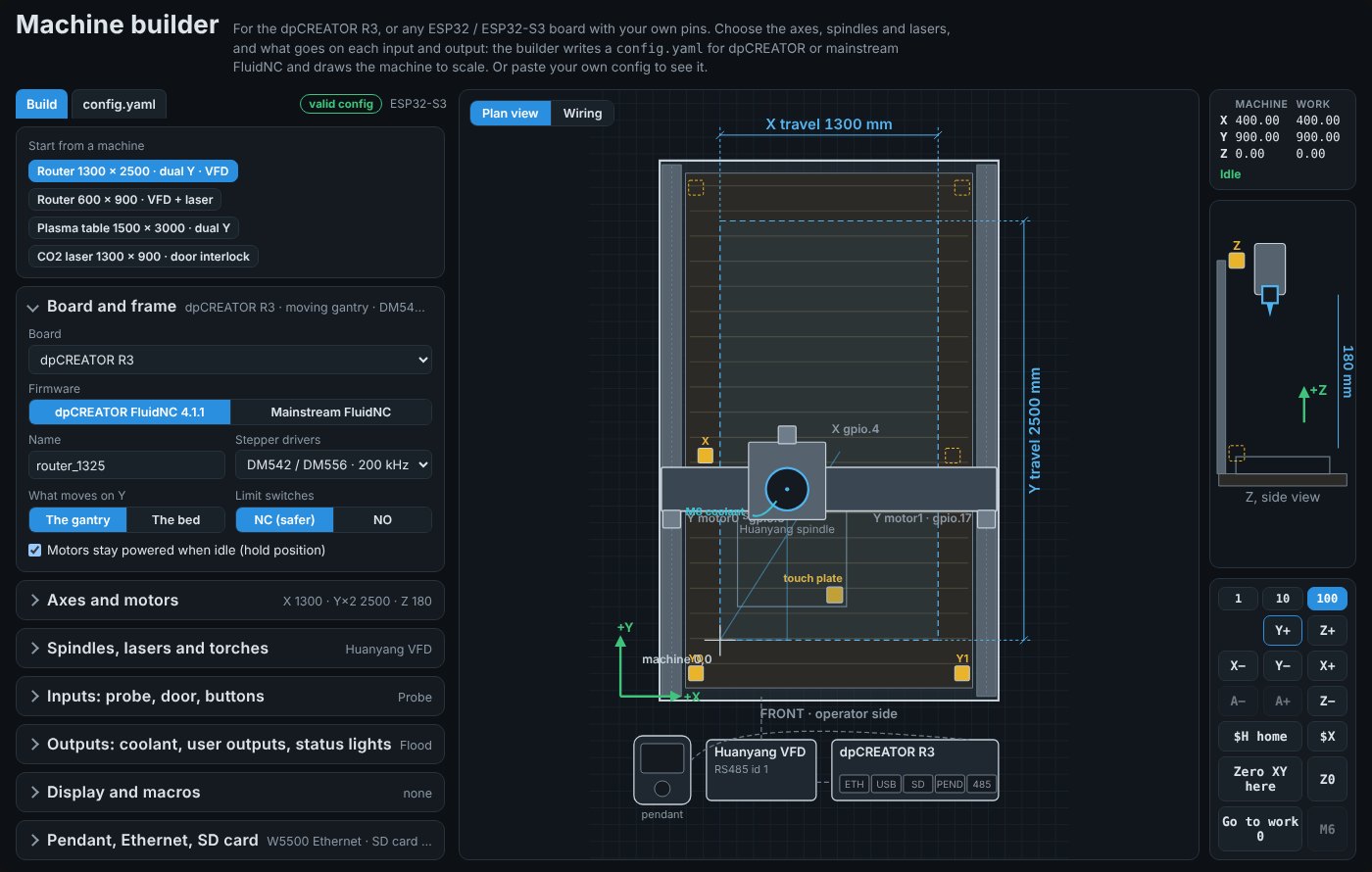
Start from a machine
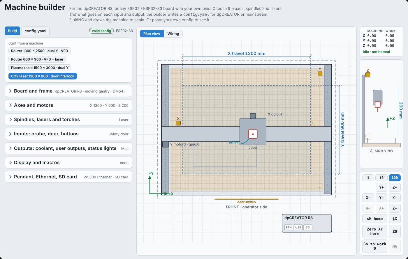
Pick the example closest to yours, then change it: a 1300 × 2500 router with dual Y and a VFD, a 600 × 900 router with a VFD and a laser, a 1500 × 3000 plasma table, or a CO2 laser with a door interlock. The summary on each section header shows what is set without opening it.
1. Board and frame
- Board: dpCREATOR R3, R2, or Other ESP32 / ESP32-S3 board (see section 8).
- Firmware: dpCREATOR FluidNC 4.1.1 or Mainstream FluidNC. Both read the same settings, except that only dpCREATOR firmware has
tools:andoffset_mm:for a second tool beside the spindle. In mainstream mode extra tools still switch with M6 by tool number; their offset is written as a comment for you to set in your sender. - Stepper drivers: sets the pulse timing and the highest step rate. Speeds above what the driver can take are capped and the builder tells you.
- What moves on Y (the gantry or the bed), limit switches NC or NO (NC is safer: a broken wire stops the machine), and whether the motors stay powered when idle.
2. Axes and motor blocks
At the top of Axes and motors you choose what each axis block drives. Any block can be any axis. The common case is a second Y motor (Y2) on the A block to square a gantry: each Y motor homes to its own switch, so homing squares the gantry every time. X2 and Z2 work the same way. A block you set to not used frees its STEP and DIR as outputs.
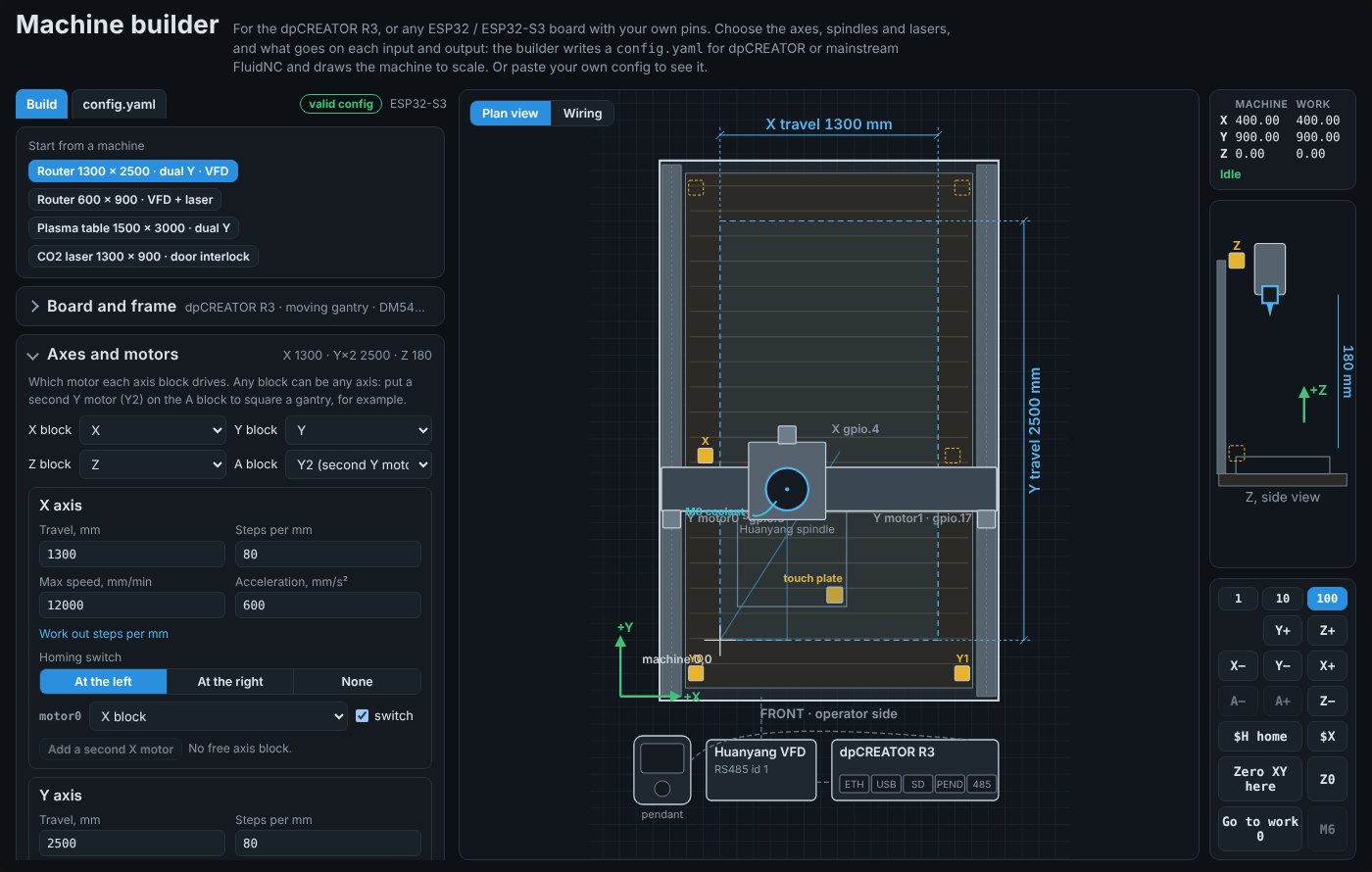
For each axis set the travel, steps per mm, speed and acceleration. Work out steps per mm calculates it for a ballscrew, belt, rack and pinion or rotary axis, with microstepping and a gearbox. Homing switch says which end the switch is at; you can also click a switch in the drawing to move it to the other end. The A axis is a rotary axis in degrees, drawn as a chuck on the bed.
3. Spindles, lasers and torches
The main tool can be a VFD over RS485 (Huanyang, H2A, H100, YL620, NowForever, Siemens V20, Danfoss VLT2800, Delta MS300, Folinn BD600, Mollom G70), a PWM or 0-10 V spindle, a relay spindle, a laser or a plasma torch (fire output, arc-OK input and arc wait). Add up to two more tools beside it, for example a laser next to the router spindle: give each a tool number and its X/Y/Z offset from the spindle, and M6 T2 switches to it.
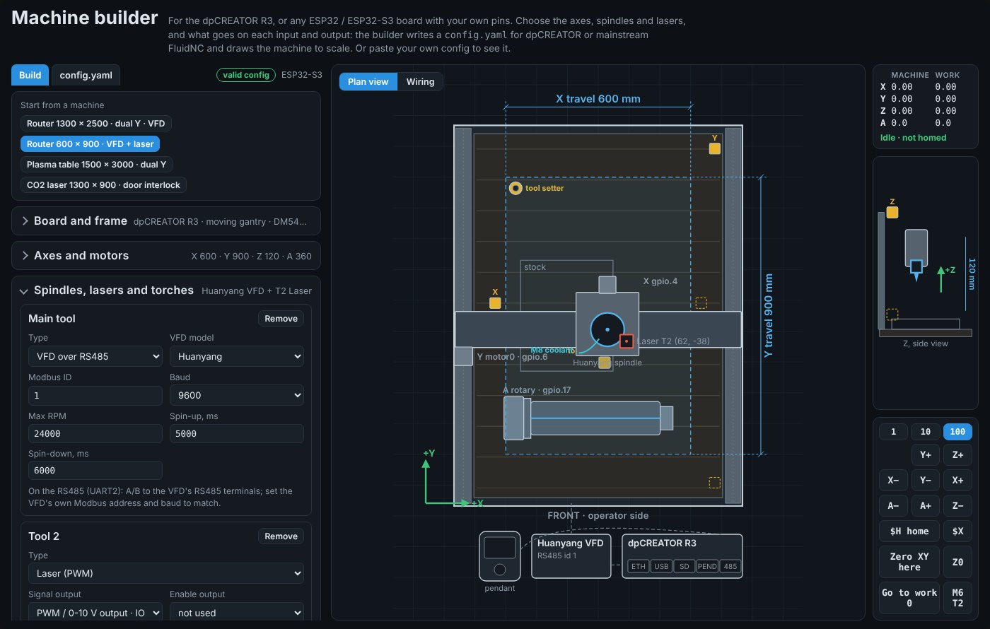
With a tool setter set under Inputs, Manual tool change adds atc_manual: M6 goes to the change position, waits for the new tool, then measures it on the tool setter. On the R3 the recommended router + laser setup is the VFD on RS485 and the laser on the PWM output; see Spindle and VFD.
4. Inputs
Every input is a list of the board's terminals: probe and tool setter; safety door, e-stop and driver fault; reset, feed hold, cycle start, home and single-block buttons; four macro buttons; four user inputs (M66). A terminal already in use is greyed out with what uses it. On the R3 the limit input of an axis block you don't use takes a switch or a button too.
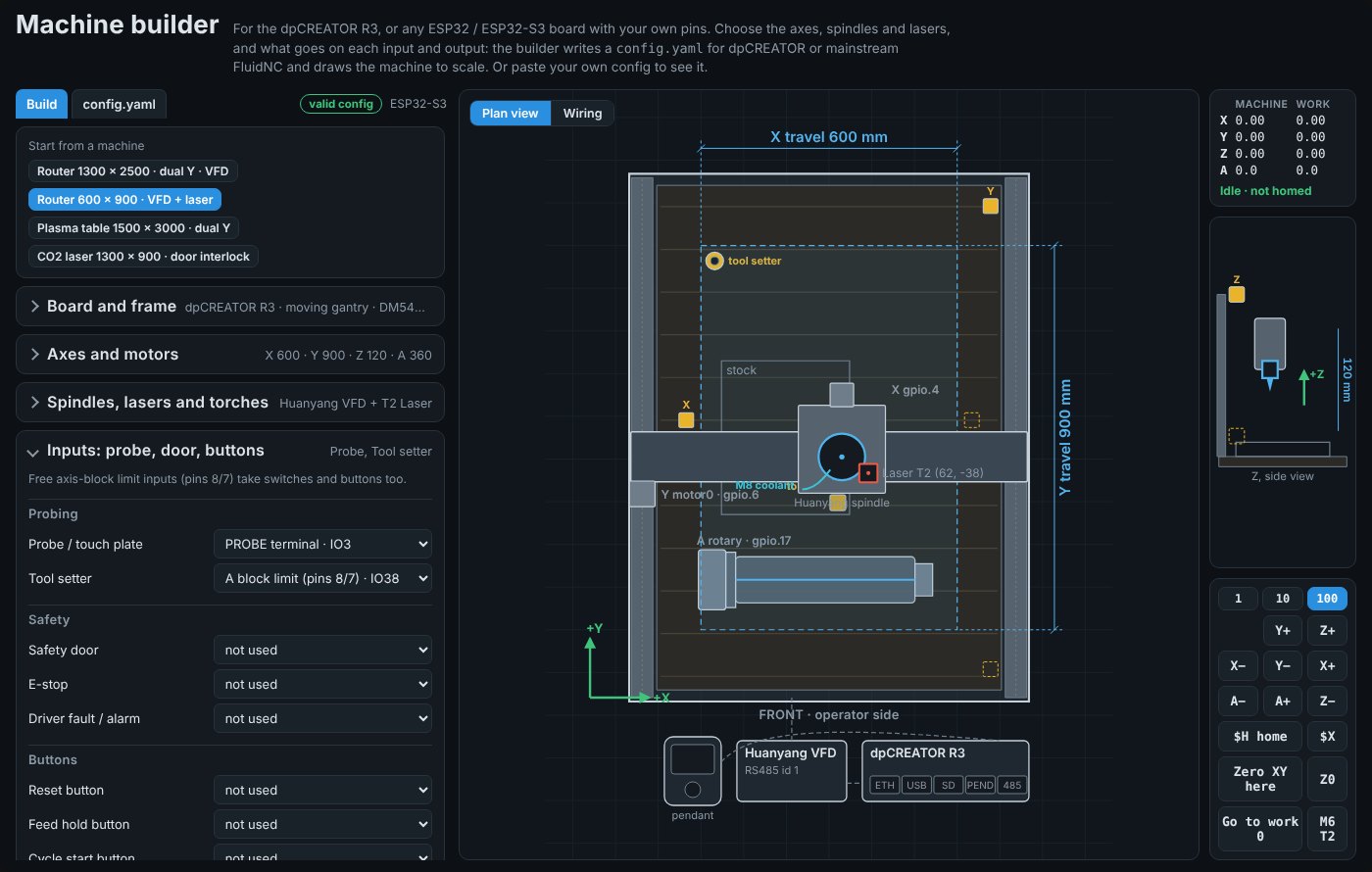
With a safety door you can turn on parking: opening the door lifts Z to a set height. The e-stop input stops the controller; it does not replace a hardwired e-stop that cuts the drivers' power.
5. Outputs and status lights
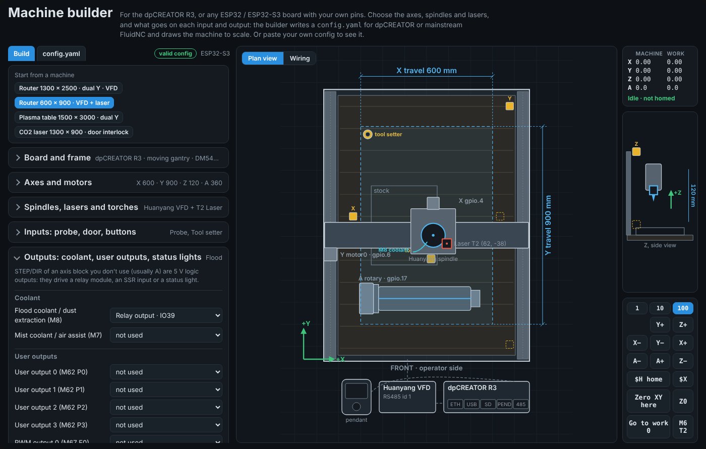
Flood (M8) and mist or air (M7), four user outputs (M62/M63) and a PWM output (M67), status lights for idle, running, hold, alarm and door, and a WS2812 RGB status LED whose colour follows the machine state. On the R3, STEP and DIR of a block you don't use (usually A) are 5 V logic outputs: they drive a relay module, an SSR input or a status light.
6. Display and macros
OLED display: an SSD1306 status screen over I2C (128 × 64, 128 × 32 or 64 × 48). It needs two plain GPIO pins; on the R3 that is the J7 connector (GPIO43/44). Using J7 for the display gives up the UART0 serial console there; USB and the network still work.
Macros: a startup line, macros 0-3 (run from a macro button or $Macros/Run=0), and lines to run after homing and after unlock. Join commands with &, for example G0 Z-5&G0 X0 Y0.
7. Pendant, Ethernet and SD card
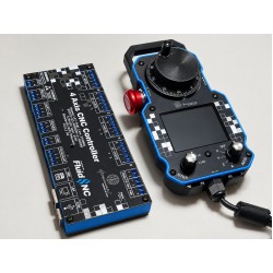
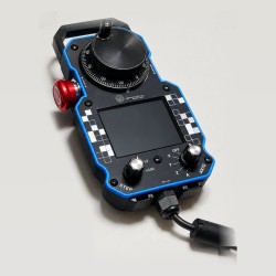
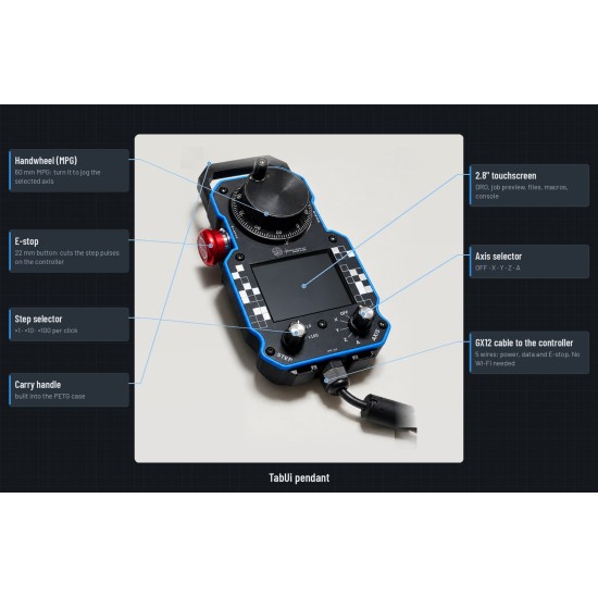
The SmartTabUI pendant on the PENDANT port, the W5500 Ethernet (SPI clock, and whether the INT line is used) or Wi-Fi only, and the SD card with its clock. The W5500 and the SD card share the SPI bus. See Ethernet (W5500) setup for the IP settings.
8. Other ESP32 and ESP32-S3 boards
Choose Other ESP32 / ESP32-S3 board and the section Your board's pins opens. Pick the chip, then the GPIO behind each terminal: STEP, DIR and limit for each block, the driver enable (active high or low), your own named inputs, outputs and I/O pins, the pendant UART, RS485, SPI, SD card and W5500. Everything else in the builder then uses those terminals.
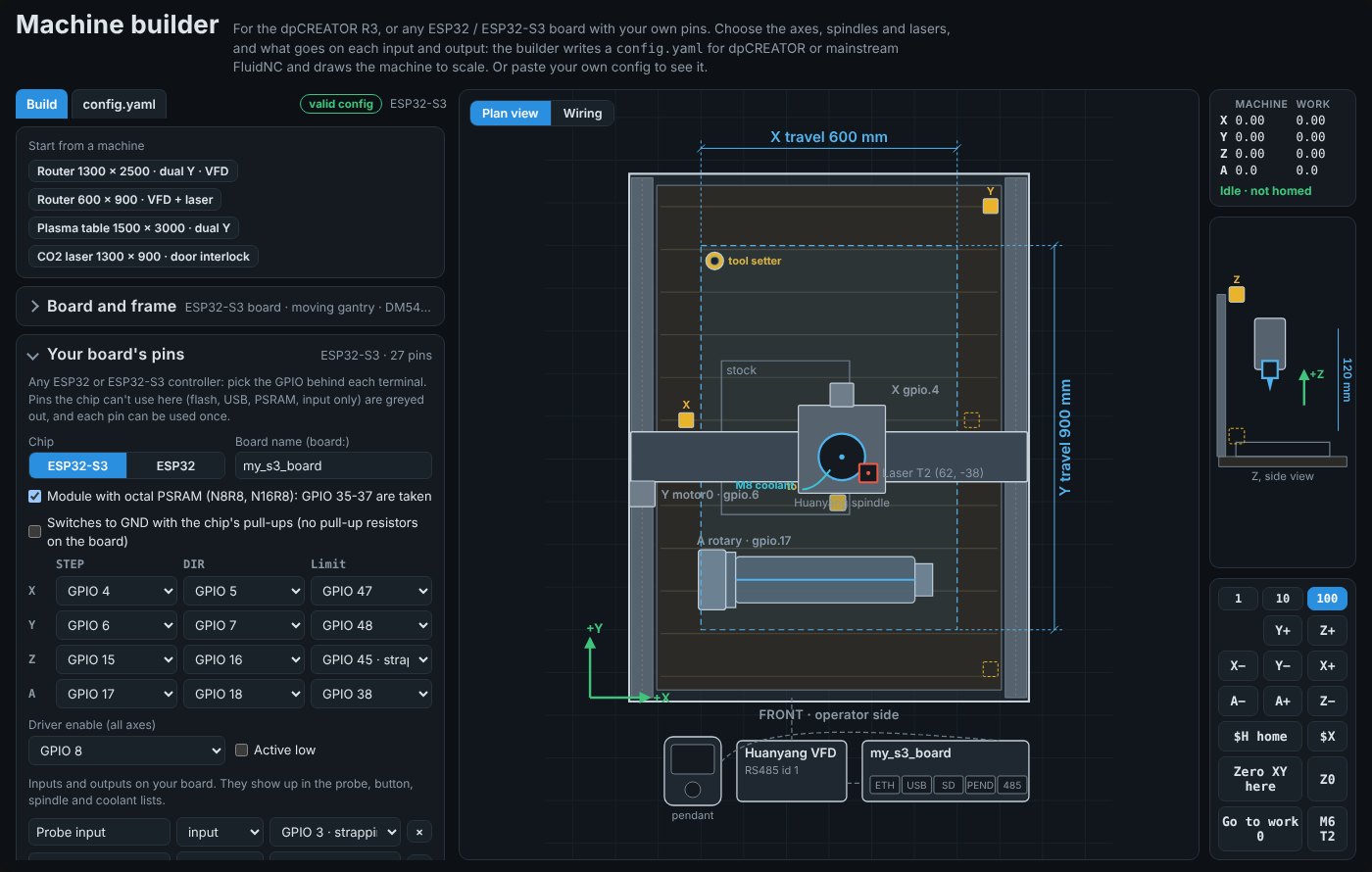
The pin lists follow the chip:
| ESP32-S3 | ESP32 | |
|---|---|---|
| Not usable | GPIO 26-32 (flash), 19/20 (USB), 35-37 on modules with octal PSRAM (N8R8, N16R8) | GPIO 6-11 (flash) |
| Input only | none | GPIO 34-39, and they have no internal pull-up |
| Strapping pins (marked) | 0, 3, 45, 46 | 0, 2, 5, 12, 15 |
Each pin can be used once; the SPI bus pins are shared by the SD card and the W5500 by design.
9. Check the config and the wiring
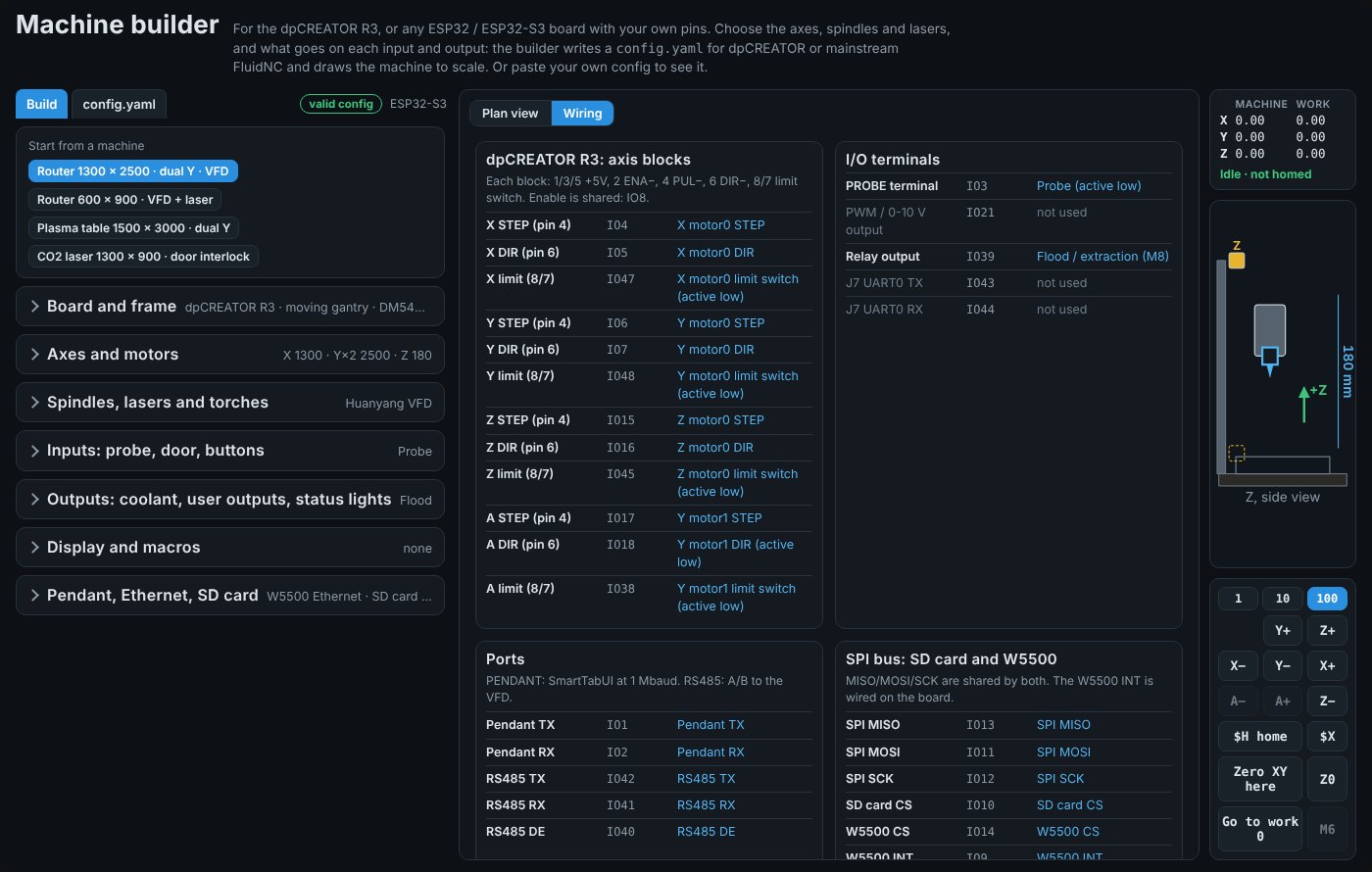
The badge next to the tabs shows whether the config is valid, and for which chip. Wiring lists every terminal of the board with what the config puts on it, marks free terminals and shows any pin used twice in red. Click a function to jump to its line.
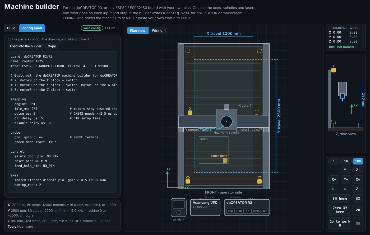
The config.yaml tab shows the file with a comment on every pin. You can edit it there, or paste your own config: the drawing, wiring and checks follow it. Load into the builder turns a pasted config back into builder settings. Configs that use things the builder can't edit (I2S shift-register pins as on the 6-Pack or MKS DLC32, TMC drivers set over UART or SPI, CoreXY and other kinematics, servos, pin extenders) stay in the text view, so nothing is lost.
10. Try it before you wire it
The jog pad and the arrow keys move the tool in the drawing. $H home runs the homing cycles in order and shows machine 0. Jog into a switch with hard limits on and you get the alarm the real machine would give. Zero XY here sets the work zero, and M6 switches between tools so you can see the offset applied.
11. Put it on the board
- Copy or save
config.yamlfrom the config.yaml tab. - Upload it to the controller: in the WebUI file manager, or on the Flash Firmware page choose I have a config.yaml, which writes it after flashing. See Flashing firmware from your browser.
- Restart with
$byeand run the first checks: jog each axis a short way, check the directions, then home.