
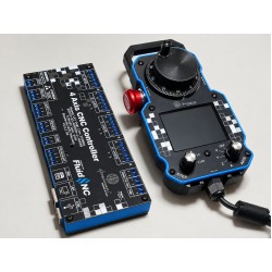
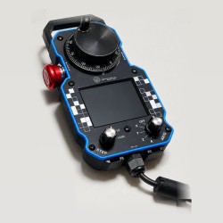
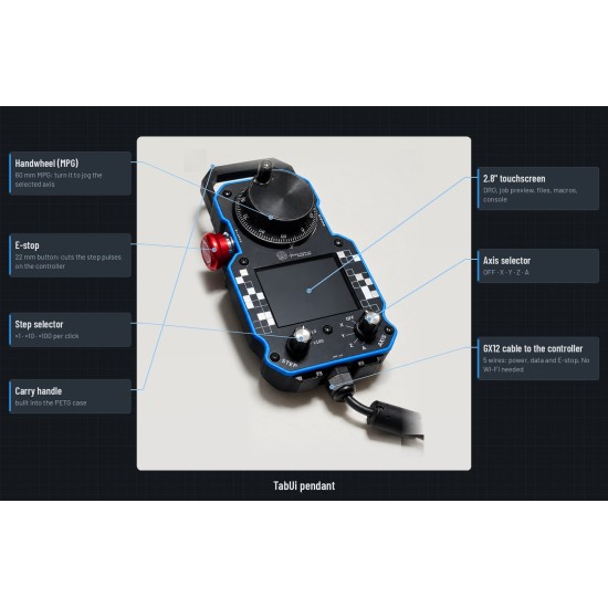
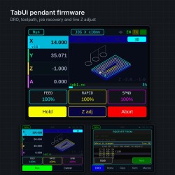
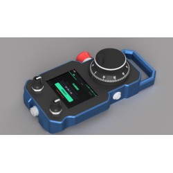
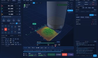
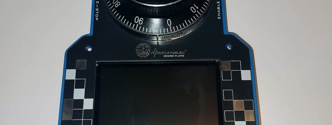
This guide takes you from the parts on the bench to a working SmartTabUI pendant. You need the SmartTabUI pendant firmware. The PETG case print files are free. Prefer it ready-made? Get the assembled pendant: every one is assembled in-house, by the designer or by experienced technicians.

What you need

| Qty | Part | Notes |
|---|---|---|
| 1 | JC2432W328C display board | 2.8" capacitive touch, 240×320, ESP32. The C (capacitive) version. |
| 1 | 60 mm MPG handwheel | ZS61-type, 100 pulses per turn, outputs A and B |
| 1 | E-stop button, 16 mm | Latching, with a change-over contact (C, NO, NC) |
| 1 | Momentary push button, 12 mm | The ENABLE button on the right side |
| 1 | Rotary switch, 3 positions | RS16 or RS26 type, for STEP |
| 1 | Rotary switch, 5 positions | RS16 or RS26 type, for AXIS |
| 2 | Knobs for the rotary switches | |
| 1 | PCF8574 I/O expander module | Reads the selectors and the ENABLE button |
| 1 | GX12 connector, 5-pin, or a PG7 cable gland | GX12: plug-in cable to the controller. PG7 gland: the cable goes straight into the case instead. |
| 1 | Printed case | Case body, top plate (closed, or with a 2 mm front panel), front panel and IO expander clip (DPC-TC1 print files) |
| 4 | M2.5 self-tapping screws | Hold the display in the front panel |
| 1 | Small speaker with JST plug | Plugs into P4 (SPEAK) |
| 7 | M3 screws (black) | Fix the front panel to the case |
| — | Hook-up wire and JST cables | For P1, P6 and CN1 on the display board |
| — | Heat-shrink tubing | Optional, to insulate the solder joints |
| — | 704 silicone rubber for electronics | Glues the display, the modules and every connection in place |
Tools: soldering iron and solder, side cutters, wire stripper, Phillips screwdriver, multimeter, USB-C cable. Optional: heat gun for heat-shrink.
1. Remove the RGB LED from the display board
The JC2432W328C has an RGB LED on the front, next to the display. It is wired to IO4, IO16 and IO17: the same pins the pendant uses on connector P6 for the handwheel and the E-stop. Left in place, it loads those lines and the inputs don't read reliably. Desolder it with a soldering iron or hot air.


2. Assemble the front panel

- Display. Peel the protective film off the display first. Place the board in the front panel and fix it with the four M2.5 self-tapping screws.
Be careful with the display connector as the board goes into the printed panel: it is a tight fit there.Then run a bead of 704 silicone around the perimeter of the board, wherever it can reach the case. Press the display down while the silicone dries and make sure it stays fully seated.
- Handwheel. Fit the 60 mm MPG through the round opening and tighten it on its three mounting studs.
- STEP selector. Fit the 3-position rotary switch (RS16 or RS26) in the left opening.
- AXIS selector. Fit the 5-position rotary switch in the right opening.

3. Assemble the main case
- Screw the E-stop button (16 mm) into the left side of the case.
- Screw the ENABLE button (12 mm) into the right side.
- Leave the GX12 connector out for now. It goes in after the wiring, so the wires are easy to reach. Using a PG7 cable gland instead? Fit it in the same hole and pass the cable through it later.

4. Wire it
Everything connects to the connectors on the back of the display board: P1 (serial and power), P6 (handwheel and E-stop), CN1 (I²C to the PCF8574) and P4 (speaker). Nothing is soldered to the board itself.

P6 → handwheel and E-stop
| P6 pin | Wire | Goes to |
|---|---|---|
| IO17 | red | E-stop button, contact C |
| IO4 | black | MPG B |
| IO16 | yellow | MPG A |
| GND | green | MPG − |
MPG + goes to 3.3 V: take it from the CN1 3.3V pin, together with the PCF8574 VCC wire.
CN1 → PCF8574 module
| CN1 pin | PCF8574 |
|---|---|
| GND | GND |
| IO22 | SCL |
| IO21 | SDA |
| 3.3V | VCC |
PCF8574 inputs → selectors and ENABLE. Every input closes to GND: wire the common of each rotary switch and one side of the ENABLE button to GND.
| Input | Function |
|---|---|
| P0 · P1 · P2 · P3 | AXIS selector: X · Y · Z · A (OFF = no contact) |
| P4 · P5 | STEP selector: ×10 · ×100 (×1 = no contact) |
| P6 | ENABLE button |
| P7 | not used |
P1 → GX12 connector (the cable to the controller). With a PG7 cable gland, connect the five cable cores to the same signals.
| GX12 pin | Signal | Wire | From |
|---|---|---|---|
| 1 | +5V | red | P1 5V |
| 2 | TXD | black | P1 TX |
| 3 | E-STOP | orange | E-stop button, contact NC |
| 4 | RXD | yellow | P1 RX |
| 5 | GND | P1 GND |
E-stop button contacts
| Contact | Goes to |
|---|---|
| C (common) | P6 IO17 |
| NO | GND |
| NC | GX12 pin 3, to the controller |


- Fix the PCF8574 module to the back of the display board with a blob of 704 silicone, clear of the ESP32 module.
- Plug the speaker into P4 (SPEAK) and fix it inside the case with a dab of silicone.
- Put a dab of silicone on the solder joints and connector plugs so they can't work loose.
- Fit the GX12 connector in the bottom of the case and solder its five wires. With a PG7 gland: pass the cable through the gland, connect the five cores, then tighten the gland so it grips the cable.
- Insulate the joints with heat-shrink (optional).
5. Close the case
Lay the wires flat so nothing is pinched, place the front panel on the case and fix it with the 7 black M3 screws. Fit the knobs on the STEP and AXIS switches so the pointer lines up with x1 and OFF.
6. Flash and test
Flash the pendant firmware over USB-C from Firmware & Downloads. Unplug the controller cable while you flash: the serial pins are shared.
The test menu. The pendant has a built-in test menu, so you can check every part of your build before it ever talks to the controller. Hold the ENABLE button during the first second of boot to open the pendant settings, then tap Inputs to open the Input Monitor.
The Input Monitor shows, live:
- the raw value of the PCF8574 and each of its inputs, P0 to P7, as HIGH or LOW (active),
- the E-stop on IO17 (open or pressed),
- the handwheel's encoder delta, which counts as you turn it,
- the touchscreen: where you touch it.
- Turn AXIS through OFF, X, Y, Z and A: P0 to P3 go LOW one at a time, and none at OFF.
- Turn STEP through x1, x10 and x100: P4, then P5 go LOW, and none at x1.
- Press ENABLE: P6 goes LOW.
- Press the E-stop, then release it: the E-stop line changes.
- Turn the handwheel both ways: the encoder delta counts up and down. If it counts the wrong way, swap the A and B wires.
- Touch the screen in a few places.
Hold the E-stop for 2 seconds to leave the Input Monitor.


7. Connect to the controller
- Plug the pendant into the controller's pendant port and power up. The controller's config.yaml needs the
uart1anduart_channel1sections at 1,000,000 baud: see Connecting the SmartTabUI pendant. - The WebUI header shows the pendant badge, and
$Pendant/Statusanswersconnected. - Test the E-stop while jogging slowly: the motors must stop at once and the machine must go to Alarm. Release it and use the recovery menu to unlock.
Already know the CYD display?
SmartTabUI runs on the JC2432W328C display (CYD) with a 60 mm handwheel, the same parts many FluidDial builders already know. If you have built with this display before, you can build on that experience. SmartTabUI has its own wiring, so leave your FluidDial pendant as it is and use a separate display for SmartTabUI, connected as in this guide. These are the display pins SmartTabUI uses:
| Display pin | SmartTabUI |
|---|---|
| IO22 | PCF8574 SCL (CN1) |
| IO21 | PCF8574 SDA (CN1) |
| IO16 | Handwheel A (P6) |
| IO4 | Handwheel B (P6) |
| IO17 | E-stop (P6) |
| TX / RX | Serial link to the controller, 1 Mbaud (P1) |