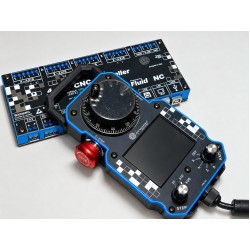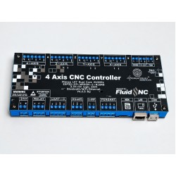
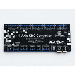
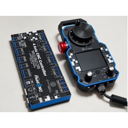
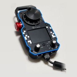
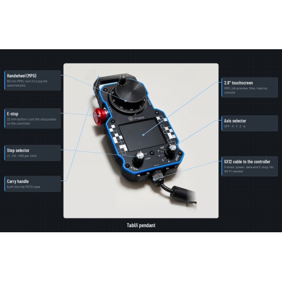
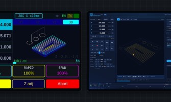
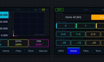
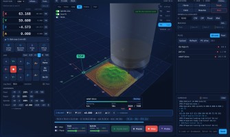
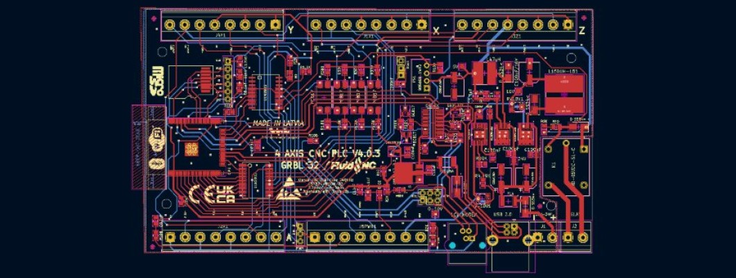
The dpCREATOR R2/R3 drives any machine that moves on step and direction signals: CNC routers and mills, lasers, plotters and drag knives, and plasma tables. Use it for a new build, or to replace an old controller and keep your drivers, motors and switches. The machine type is set in config.yaml, and the SmartTabUI pendant has CNC, laser and plotter modes in its settings.
Retrofit an existing machine
The four axis outputs are 5 V step, direction and enable signals. They suit most external stepper drivers (DM542 / DM556 type, TB6600 type, closed-loop steppers) and AC servo drives in step/direction mode. Typical upgrades are a Mach3 parallel-port breakout board, an old GRBL board, or a closed controller that is no longer supported.
Wiring drivers with opto inputs
| Driver input | R2/R3 |
|---|---|
| PUL+ (STEP+) | Step output of the axis |
| DIR+ | Direction output of the axis |
| ENA+ | Shared enable (GPIO8) |
| PUL−, DIR−, ENA− | GND |
Pin numbers for each axis are on the pinout page.
Timing for opto-input drivers
Drivers such as the DM542 need the direction signal set a few microseconds before the step pulse. Give them more time than the example config does:
stepping:
  engine: RMT
  pulse_us: 4
  dir_delay_us: 5
Checklist
- Enable: if the motors stay free when they should hold, or hold when disabled, invert the enable with
shared_stepper_disable_pin: gpio.8:low. - Direction: if an axis moves the wrong way, add
:lowto itsdirection_pin. - Steps per mm: set
steps_per_mmfrom your driver's microstep setting and the mechanics. The example values are placeholders. - Switches: the limit inputs are opto-isolated. Add or remove
:lowto match normally-open or normally-closed switches. - First test: run with the belts or couplings loose, at low speed, with the E-stop in reach.
CNC router or mill
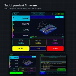
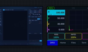
This is the example config: four axes, the spindle on the PWM output with the relay as on/off, or a VFD over RS485. See Spindle and VFD. On the pendant, the FEED, RAPID and SPND boxes set the overrides.
Laser
Replace the PWM: section with a Laser: section. The laser power comes from the PWM output and the relay switches the laser enable:
Laser:
  pwm_hz: 5000
  output_pin: gpio.21
  enable_pin: gpio.39
  tool_num: 0
  speed_map: 0=0.000% 1000=100.000%
Use M4 (laser mode) in your CAM or LightBurn, set up as a GRBL device with S max 1000. In M4 the power follows the real speed, so corners and slow moves don't burn darker. Set the pendant to Laser mode and its third box shows the laser power.
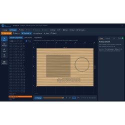
M4 needs the Laser: section. With only a router spindle (PWM:, 10V: or a VFD) M4 stops the job with error 20 (Unsupported GCode command): use M3, or add the laser as in Router and laser on one machine below. Laser jobs show as a burn in the WebUI's Part view and the pendant's PART view, and the WebUI run bar shows the laser power.
Safety: run lasers in an enclosure with the right eyewear. Wire the enclosure interlock to a spare input as control: safety_door_pin.
Router and laser on one machine
A laser module next to the router can be a second spindle with its own tool number: M6 T2 selects the laser, M6 T1 (or any router tool) the router. You don't need a tool changer. The controller stops the one that was running and applies the laser's offset from the router bit, so one work zero serves both: after switching, the work position shows where the laser spot is.
This needs the dpCREATOR firmware from build 13cbee6e on, and the latest WebUI and SmartTabUI firmware.
Which wiring on the R3
The R3 has no spare GPIO, so the router's speed signal decides where the laser goes:
| Router | Laser | A axis | |
|---|---|---|---|
| Recommended | Inverter (VFD) over RS485 | PWM output (gpio.21) for power, relay (gpio.39) for laser enable or air assist | Free to use |
| Possible | Inverter on the 0-10V output (gpio.21), relay (gpio.39) on its FWD/run input | A-axis STEP output (gpio.17), 5 V logic | Not available |
With a 0-10V inverter and an A axis (for example a rotary), no output is left for the laser: use RS485 for the router. Two spindles can't share one output pin, and the R3's single relay is needed for the inverter's run input, so the relay can't switch one signal between the inverter and the laser.
Recommended: RS485 inverter + laser on PWM
Huanyang:                 # RS485 wiring and uart1: see the Spindle and VFD page
  uart_num: 1
  modbus_id: 1
  tool_num: 0             # every tool not listed elsewhere: T1, T3, T4...
  speed_map: 0=0% 24000=100%

Laser:
  pwm_hz: 5000
  output_pin: gpio.21
  enable_pin: gpio.39
  tools: 2                # M6 T2 selects the laser
  offset_mm: 42.5 18 0    # laser spot from the router bit: X Y Z (mm)
  speed_map: 0=0% 1000=100%
Use the section for your inverter (Huanyang, H2A, YL620, ModbusVFD...) as on the Spindle and VFD page.
Possible: 0-10V inverter + laser on the A-axis STEP output
Only for machines without an A axis. Remove the a: axis from config.yaml, then:
10V:
  output_pin: gpio.21     # 0-10V speed signal
  forward_pin: gpio.39    # relay: inverter FWD / run
  tool_num: 0
  spinup_ms: 3000
  spindown_ms: 3000
  speed_map: 0=0% 24000=100%

Laser:
  pwm_hz: 5000
  output_pin: gpio.17     # A-axis STEP output
  tools: 2
  offset_mm: 42.5 18 0
  speed_map: 0=0% 1000=100%
The STEP output is 5 V logic, which suits the TTL/PWM input of most diode lasers. It goes through the board's 3.3 V → 5 V level shifter: if that stage inverts the signal, write gpio.17:low so that S0 means laser off. Check with a meter or a scope before connecting the laser.
The two new settings
tools:the exact tool numbers that select this spindle, e.g.2or2 9. The other tools stay on the router.offset_mm:where the laser spot is relative to the router bit, X Y Z in mm.42.5 18 0means 42.5 mm to the right (+X) and 18 mm behind (+Y). Z is how far the laser's focus point is above the bit's tip (negative if below).
Measuring the offset
- With the router, set a work zero and cut a small cross, e.g. 0.5 mm deep at X50 Y50.
- Put the bit exactly over the centre of the cross and note the Machine X and Y in the WebUI.
- Switch to the laser (M6 T2 or T2 laser in the WebUI's tool column). Jog until the laser spot (low power or the pointer) is on the centre of the cross, and note the machine X and Y.
- Offset X = bit X − laser X, offset Y = bit Y − laser Y. For Z: offset Z = machine Z with the bit touching the surface − machine Z with the laser focused on it.
- Put the values in
offset_mm:, restart the controller, switch to T2 and check that X50 Y50 puts the laser spot on the cross.
Using it
- Switching: M6 T2 in a file or the console, or T2 laser in the WebUI's tool column. The router stops, nothing is measured, and the work position jumps by the offset. M6 T1 switches back. With a tool setter, router tools are measured as usual.
- Jobs: start laser files with
M6 T2(add it as a header in LightBurn or your CAM) and router files withM6 T1. - WebUI: the run bar shows Laser with the power in % and the S value. The 3D view shows the laser module, and the Part view shows the burn.
- Pendant: the third override box reads LASER while the laser is selected. The PART view shows the burn.
- G49 clears a tool length but keeps the laser offset. After a reset the selected spindle's offset is applied again.


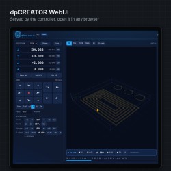
With T2 selected, the WebUI shows T2 Laser and the work position of the laser spot; the pendant reads LASER.
Plotter or drag knife
Put the pen or knife on the Z axis: depth is then a normal Z move from your CAM. In Plotter mode the pendant shows the Z depth in its third box, so you see at a glance whether the pen is up or the knife is cutting.
For a light pen lift, a hobby servo works too. This example drives it from the A step output, so the A axis is not used:
  z:
    steps_per_mm: 100
    max_rate_mm_per_min: 5000
    acceleration_mm_per_sec2: 500
    max_travel_mm: 5
    motor0:
      rc_servo:
        output_pin: gpio.17
        pwm_hz: 50
        min_pulse_us: 1000
        max_pulse_us: 2000
Adjust the pulse range to your servo.
Plasma table
FluidNC's PlasmaSpindle fires the torch from the relay output and waits for the cutter's arc-OK signal before the machine moves. If the arc doesn't start in time, it stops with an alarm.
PlasmaSpindle:
  enable_pin: gpio.39
  arc_ok_pin: gpio.38:low
  arc_wait_ms: 1500
  tool_num: 0
This example takes arc OK on the A limit input, which is opto-isolated, so set the A axis limit to NO_PIN or remove the A axis. Connect it to the dry arc-OK contact on your plasma cutter's CNC port.
- Torch height: there is no built-in torch height control (THC). If your table needs one, use a standalone THC unit.
- Noise: plasma is electrically noisy. Use shielded step and switch cables, ground the table well, and keep the torch lead away from signal cables.
- E-stop: the pendant E-stop cuts the step pulses on the board. Also fit an E-stop that cuts the plasma cutter's power.
Related Products