
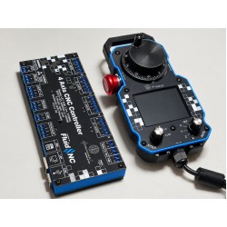
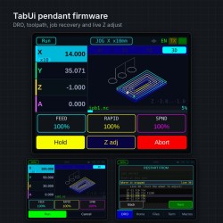
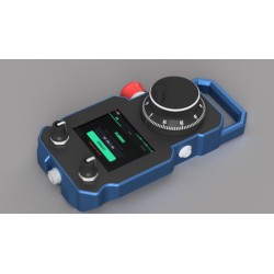
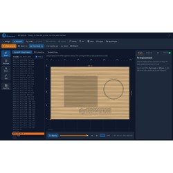
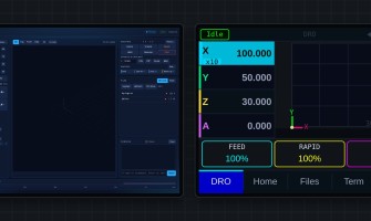
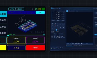
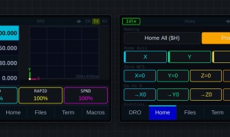

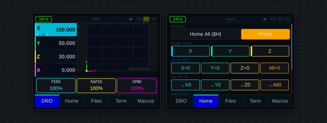
The SmartTabUI pendant connects to the controller with a wired serial link (UART1), not over the network. It keeps working when Wi-Fi or Ethernet drops.

Hardware
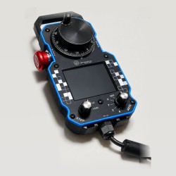
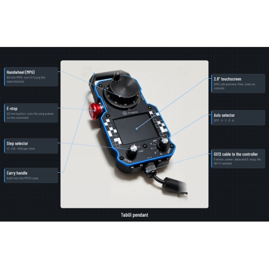
- JC2432W328C board: ESP32, 2.8" 320×240 touchscreen
- MPG handwheel (quadrature encoder) on GPIO16 / GPIO4
- E-stop button on GPIO17 (active low)
- Optional axis and step selector switches through a PCF8574 I/O expander
Wiring
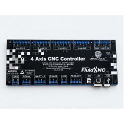
The pendant connects with a GX12 5-pin connector and a five-core cable, all on the controller's pendant port:
- TX / RX — serial link (controller GPIO1 / GPIO2), crossed over
- 5V / GND — pendant power
- E-STOP — the pendant E-stop button pulls this line to GND; the controller then disables the step pulses in hardware
Keep the cable short and shielded; a noisy cable shows up as dropped bytes (see Troubleshooting). Building your own pendant? See Build your SmartTabUI pendant: assembly and wiring.
config.yaml
The example config already contains this. Both ends must use the same baud rate (1,000,000).
uart1:
  txd_pin: gpio.1
  rxd_pin: gpio.2
  rts_pin: NO_PIN
  cts_pin: NO_PIN
  baud: 1000000
  mode: 8N1

uart_channel1:
  uart_num: 1
  report_interval_ms: 75
  message_level: Info
Check the connection
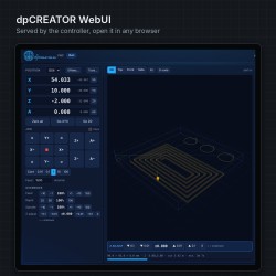
- The WebUI header shows a pendant badge when it is connected.
$Pendant/Statusanswersconnected,disconnectedornone(nouart_channel1in the config).- An unplugged pendant is noticed within about 3 seconds while the machine is idle.

Pendant settings
Hold the EN button while the 5-second bar runs at start-up to open the pendant's settings: theme, EN button mode, DRO axes, backlight, speaker volume, maintenance reminder, and the licence with the pendant's chip ID. Machine settings (work area, home corner) come from the controller's config.yaml. See SmartTabUI pendant: screens, jogging and settings.
Flash both: pendant and controller firmware are developed together. After updating one, update the other — see Flash Firmware.