
12 Oct
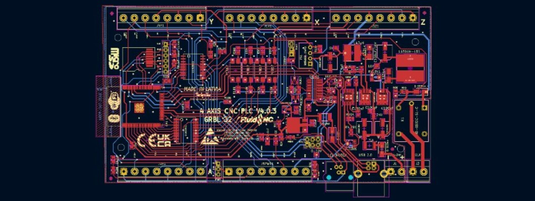
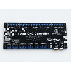
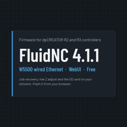
The dpCREATOR R2 and R3 share one pinout. The table below matches the example config dpcreator_r2_r3_w5500.yaml that ships with the firmware.

Main features
- ESP32-S3-WROOM-1-N16R8: 16 MB flash, 8 MB PSRAM
- 4 axes (X, Y, Z, A) — step/dir outputs for external stepper or servo drivers, shared enable
- Opto-isolated limit inputs, probe input
- Spindle: PWM output plus relay (on/off); RS485 for Modbus VFDs
- W5500 wired Ethernet, Wi-Fi, USB
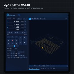
- SD card, shared over the network as a drive
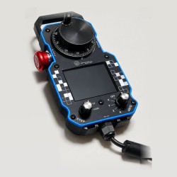
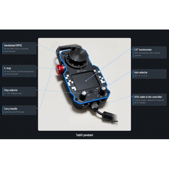
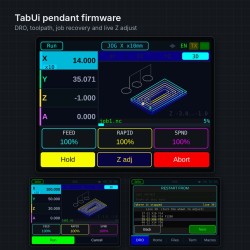
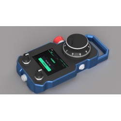
- Pendant port (UART1)
- R3 vs R2: R3 uses an integrated 5 V power module and has a separate probe input on GPIO3 (on R2 the probe shares GPIO45 with the Z limit).
Pin assignments
| Function | Pins (GPIO) | Notes |
|---|---|---|
| X step / dir | 4 / 5 | Limit X: 47 (active low) |
| Y step / dir | 6 / 7 | Limit Y: 48 |
| Z step / dir | 15 / 16 | Limit Z: 45 (shared with probe on R2) |
| A step / dir | 17 / 18 | Limit A: 38. Rotary: steps per degree |
| Stepper enable (all) | 8 | Add :low if your drivers enable on low |
| Probe | 3 (R3) | R2: GPIO45, instead of the Z limit |
| Spindle PWM / relay | 21 / 39 | 5 kHz PWM, relay as spindle enable |
| RS485 (UART2) TX / RX / DE | 42 / 41 / 40 | 9600 baud default, for Modbus VFDs |
| Pendant (UART1) TX / RX | 1 / 2 | 1,000,000 baud |
| SPI SCK / MOSI / MISO | 12 / 11 / 13 | Shared by SD card and W5500 |
| SD card CS | 10 | |
| W5500 CS / INT | 14 / 9 | INT optional — use NO_PIN if not wired |
| Console (UART0) | 43 / 44 | 115200, connector J7. USB console on GPIO19/20 |
Before you cut: set steps_per_mm for your mechanics. The example values (400 for X/Y/Z, 44.444 for A) are placeholders.
Wiring overview
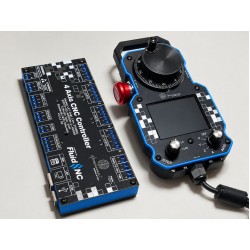
How a typical CNC router connects: each axis driver and its limit switch share the axis terminal; the spindle runs from a VFD over RS485 (or 0–10 V / PWM), the relay switches a contactor or dust extraction, and the SmartTabUI pendant plugs into PENDANT with its GX12 cable.
