


Description
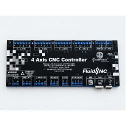
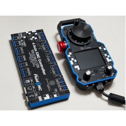
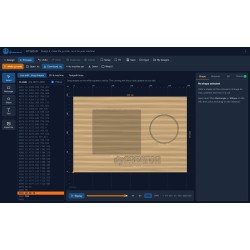
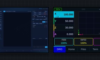
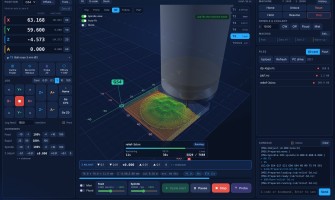
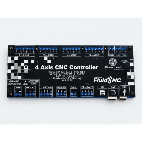
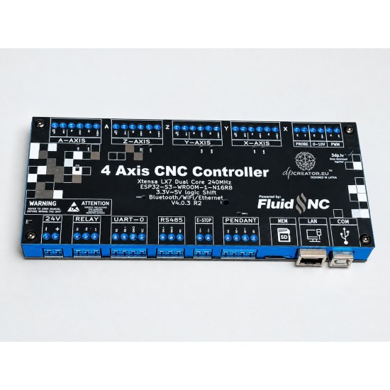
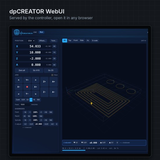
A 4-axis CNC controller built around FluidNC, with wired Ethernet, the dpCREATOR WebUI included and a dedicated pendant port. Shipped flashed with the latest firmware and tested.
For any step/dir machine: CNC routers and mills, lasers, plotters and drag knives, and plasma tables. It also retrofits machines that already have drivers taking 5 V step and direction signals. See Machine types and retrofits.
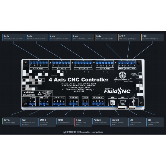
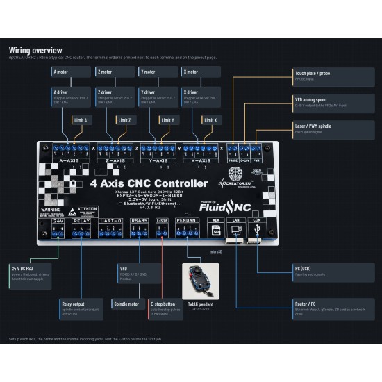
The board, terminal by terminal
Tap a terminal to see what it does, the ESP32-S3 pin behind it and how to wire it.
3.3 V → 5 V logic shift · FluidNC
Every axis block takes an external stepper driver; the rows above and below hold the inputs, outputs, buses and power.
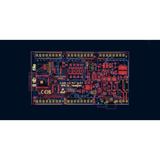
Drawing of the V4.0.3 board, not to scale. The same pins are in the config the Flash Firmware page makes for you.
Comes from the board's isolated supply. A switch goes between LIMIT and LIMIT COM; an NPN sensor's blue wire and its supply's − go here.
Switches and NPN sensors connect directly. A PNP sensor needs a PNP-to-NPN converter or a small relay.
0 V of the board. On an axis block: PUL− and DIR− of the driver.
Level-shifted from 3.3 V to 5 V. Goes to DIR+ of the driver; DIR− goes to GND. Wrong direction: add :low in the config, no rewiring.
Level-shifted from 3.3 V to 5 V. Goes to PUL+ (STEP+) of the driver; PUL− goes to GND. Leave ENA unconnected. A block without a driver can drive hobby servos or 5 V signals instead.
Plate or setter between PROBE and GND. Test with ?: Pn:P appears when it touches.
To the VFD's analog input, GND to its common. Same signal as PWM.
5 kHz by default. Same signal as 0–10V: use one or the other.
From a CE-marked 24 V DC supply. Never mains.
24 V DC. The board makes its own 5 V and 3.3 V.
A dry contact. Put COM and NO in the + wire of a contactor, valve, light or dust extraction, powered from its own supply.
The moving contact. Switches between NO and NC.
Closed while the relay is off.
The FluidNC console at 115200 baud. Reserved for GPIO expansion. USB works as the console too.
For the pendant or a small module on the same connector.
A, B and GND to the VFD (Huanyang, YL620 and others) or a Modbus I/O module with 8 inputs and 8 outputs. UART2 TX / RX / DE.
STEP and DIR only reach the drivers while E_STOP has 3.3 V. Wire a normally closed emergency-stop button between E_STOP and +3.3V, or a bridge on the bench. Open = no step pulses. Your machine still needs its own emergency-stop circuit that cuts the drives and the spindle.
Goes through the normally closed button back to E_STOP.
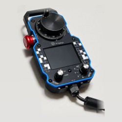
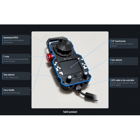
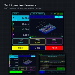
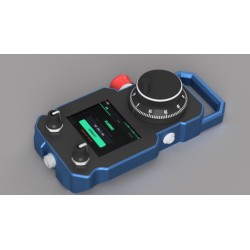
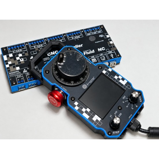
UART1 at 1,000,000 baud, with 5 V for the pendant. GX12 cable.
Shared on your network as a drive. On the SPI bus with the W5500: SCK 12, MOSI 11, MISO 13.
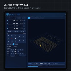
The WebUI, gSender and file transfer over your network. INT on GPIO 9.
The Flash Firmware page uses this port. Native USB of the ESP32-S3 (GPIO 19 / 20).
Specifications
| Processor and firmware | |
|---|---|
| Module | ESP32-S3-WROOM-1-N16R8: dual-core 240 MHz, 16 MB flash, 8 MB PSRAM |
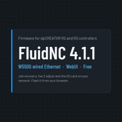
| Firmware | dpCREATOR FluidNC (FluidNC 4.1.1 with job recovery, live Z adjust, W5500 Ethernet). Updates in the browser, free |
| Step generation | RMT, straight from the ESP32-S3 pins |
| Motion | |
| Axes | 4 (X, Y, Z, A), each on a 6-way terminal block for an external driver |
| Driver signals | STEP and DIR at 5 V (level-shifted from 3.3 V); drivers stay enabled |
| Hardware enable | E-STOP input: STEP and DIR are cut while its loop is open |
| Inputs and outputs | |
| Limit inputs | 4, isolated, with their own isolated ground (LIMIT COM). Switches and NPN sensors |
| Probe | Separate PROBE input |
| Spindle and laser | PWM (5 kHz) or 0–10 V on one signal · on-board relay (NO / COM / NC) · RS485 Modbus for VFDs |
| Expansion | Modbus I/O modules on RS485 · UART-0 reserved for GPIO expansion |
| Connections | |
| Network | W5500 wired Ethernet, Wi-Fi |
| USB | Native USB of the ESP32-S3: flashing and console |
| Storage | microSD, shared on the network as a drive |
| Pendant | PENDANT connector: UART1 at 1 Mbaud + 5 V, for the SmartTabUI pendant |
| Power | |
| Supply | 24 V DC on the 24V terminal, integrated 5 V power module |
Wiring the three things every machine has
Pin map and an example config
| Function | GPIO | Notes |
|---|---|---|
| X step / dir / limit | 4 / 5 / 47 | |
| Y step / dir / limit | 6 / 7 / 48 | |
| Z step / dir / limit | 15 / 16 / 45 | On the R2 the probe shares 45 |
| A step / dir / limit | 17 / 18 / 38 | Rotary: steps per degree |
| Probe | 3 | |
| PWM / 0–10 V · relay | 21 · 39 | One signal for PWM and 0–10 V |
| RS485 TX / RX / DE | 42 / 41 / 40 | UART2, 9600 baud by default |
| Pendant TX / RX | 1 / 2 | UART1, 1,000,000 baud |
| SPI SCK / MOSI / MISO | 12 / 11 / 13 | SD card CS 10 · W5500 CS 14, INT 9 |
| UART-0 TX / RX | 43 / 44 | Console, 115200 baud |
Example config.yaml for a 3-axis router
# dpCREATOR R3 (V4.0.3): example config.yaml for a 3-axis router.
# Wiring: each axis terminal STEP 5V -> driver PUL+, DIR 5V -> DIR+, GND -> PUL- and DIR-, ENA unconnected.
# Limit switch between LIMIT and LIMIT COM. NC e-stop between E_STOP and +3.3V (no step pulses without it).
# Before homing, send ? and press each switch: Pn: shows X, Y or Z. If it shows without pressing, flip :low.
# Set steps_per_mm, speeds and travel for your machine. The Flash Firmware page builds this for you.
board: dpCREATOR R2/R3
name: dpcreator_r3_example
meta: ESP32-S3-WROOM-1-N16R8, FluidNC 4.1.1 + W5500

stepping:
  engine: RMT
  idle_ms: 250
  pulse_us: 3                  # DM542 needs >=2.5 us pulses
  dir_delay_us: 5              # DIR setup time
  disable_delay_us: 0

probe:
  pin: gpio.3:low
  check_mode_start: true

control:
  safety_door_pin: NO_PIN
  reset_pin: NO_PIN
  feed_hold_pin: NO_PIN
  cycle_start_pin: NO_PIN

axes:
  shared_stepper_disable_pin: gpio.8 # board enable line; the axis terminals have no ENA

  x:
    steps_per_mm: 80           # 20T pulley, 2 mm belt at 1/8 = 80
    soft_limits: true          # refuse moves outside the travel (needs homing)
    max_rate_mm_per_min: 3000
    acceleration_mm_per_sec2: 200
    max_travel_mm: 600
    homing:
      cycle: 2
      mpos_mm: 0               # switch position = machine 0, travel runs 0 to +600
      feed_mm_per_min: 200
      seek_mm_per_min: 2400
      settle_ms: 250
      positive_direction: false # switch at the left

    motor0:
      limit_all_pin: gpio.47:low
      hard_limits: true        # stop at once if a switch trips during motion
      pulloff_mm: 2
      standard_stepper:
        direction_pin: gpio.5
        step_pin: gpio.4

  y:
    steps_per_mm: 80           # 20T pulley, 2 mm belt at 1/8 = 80
    soft_limits: true          # refuse moves outside the travel (needs homing)
    max_rate_mm_per_min: 3000
    acceleration_mm_per_sec2: 200
    max_travel_mm: 400
    homing:
      cycle: 2
      mpos_mm: 0               # switch position = machine 0, travel runs 0 to +400
      feed_mm_per_min: 200
      seek_mm_per_min: 2400
      settle_ms: 250
      positive_direction: false # switch at the front

    motor0:
      limit_all_pin: gpio.48:low
      hard_limits: true        # stop at once if a switch trips during motion
      pulloff_mm: 2
      standard_stepper:
        direction_pin: gpio.7
        step_pin: gpio.6

  z:
    steps_per_mm: 400          # 2 mm lead at 1/4 = 400
    soft_limits: true          # refuse moves outside the travel (needs homing)
    max_rate_mm_per_min: 1000
    acceleration_mm_per_sec2: 100
    max_travel_mm: 100
    homing:
      cycle: 1
      mpos_mm: 0               # switch position = machine 0, travel runs 0 to -100
      feed_mm_per_min: 100
      seek_mm_per_min: 800
      settle_ms: 250
      positive_direction: true # switch at the top

    motor0:
      limit_all_pin: gpio.45:low
      hard_limits: true        # stop at once if a switch trips during motion
      pulloff_mm: 2
      standard_stepper:
        direction_pin: gpio.16
        step_pin: gpio.15

uart1:
  txd_pin: gpio.1
  rxd_pin: gpio.2
  rts_pin: NO_PIN
  cts_pin: NO_PIN
  baud: 1000000                # SmartTabUI pendant firmware runs at 1000000
  mode: 8N1

uart_channel1:
  uart_num: 1
  report_interval_ms: 75
  message_level: Info

spi:
  miso_pin: gpio.13
  mosi_pin: gpio.11
  sck_pin: gpio.12

sdcard:
  cs_pin: gpio.10
  card_detect_pin: NO_PIN
  frequency_hz: 4000000

ethernet:
  cs_pin: gpio.14
  int_pin: gpio.9
  rst_pin: NO_PIN
  phy_type: w5500
  phy_addr: 1
  frequency_hz: 8000000        # shared bus with the SD card

macros:
  startup_line0:
  startup_line1:
  macro0:
  macro1:
  macro2:
  macro3:

start:
  must_home: true

coolant:
  mist_pin: NO_PIN
  flood_pin: NO_PIN

PWM:
  pwm_hz: 5000
  output_pin: gpio.21
  enable_pin: NO_PIN
  direction_pin: NO_PIN
  disable_with_s0: false
  s0_with_disable: true
  spinup_ms: 3000
  spindown_ms: 3000
  tool_num: 0
  speed_map: 0=0.000% 24000=100.000%
The example passes the firmware's own settings check. Set steps/mm, speeds and travel for your machine before the first move.
How it compares
Three FluidNC boards a maker is likely to look at. The dpCREATOR firmware runs on all three.
| dpCREATOR R3 | MKS DLC32 V2.1 | 6 Pack External | |
|---|---|---|---|
| Chip | ESP32-S3, 16 MB flash, 8 MB PSRAM | ESP32 (WROOM-32) | ESP32 on a plug-in DevKitC module |
| Axes | 4 | 3 | 6 |
| Motor drivers | External, 5 V STEP / DIR on terminals | Plug-in driver modules on the board | External, 5 V signals |
| Step outputs | Straight from the chip (RMT) | Through an I2S shift register | Through an I2S shift register |
| Limit inputs | 4, isolated | 3 | 6, opto-isolated |
| Wired Ethernet | Yes, W5500 | No, Wi-Fi | No, Wi-Fi |
| Spindle and VFD | PWM, 0–10 V, relay and RS485 on the board | PWM, made for lasers | Plug-in modules: 0–10 V, RS485, relay |
| Supply | 24 V | 12–24 V | 9–24 V |
| Pendant connector and E-STOP enable | Yes | No | No |
Other boards: from their makers' pages and the FluidNC community config files, October 2026. Check the makers' pages for current details.
Documentation and files
- Pinout and featuresEvery connector, with the R2 differences
- Quick startFirst power-up, wiring, first move
- Machine types and retrofitsRouters, lasers, plasma, older machines
- Flash FirmwareFirmware, config, apps and network over USB
- dpCREATOR MotionBuild any machine on the R3, free with it
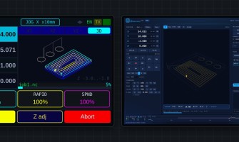
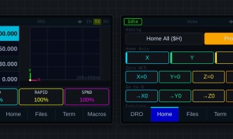
- Live demoThe pendant and the WebUI in your browser
Photos show the R2 controller. The R3 has the same layout and connectors.
Connections and wiring


Want the pendant too? The R3 + SmartTabUI combo saves €40.98.